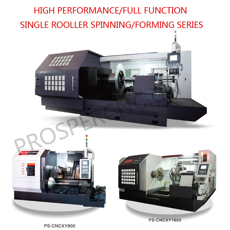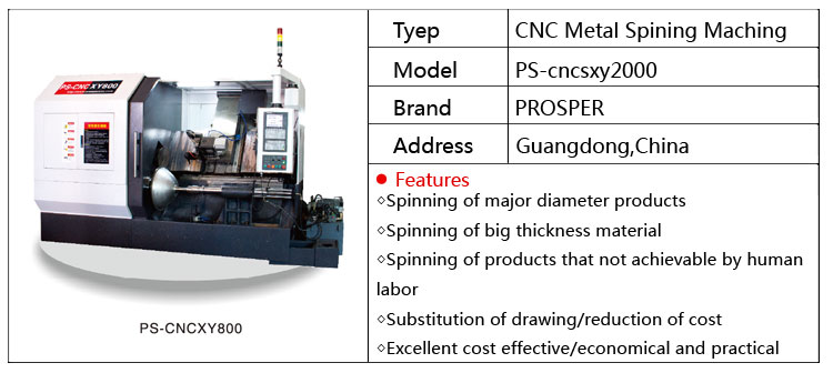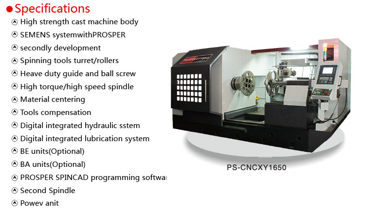
Metal spinning has several iterations that suit different applications, and among them all, multi-pass spinning remains the most common. Performed either manually or on a CNC spinning lathe, a roller sweeps across the spinning disk multiple times, shaping the metal against the mandrel.
Another common iteration, shear forming, finishes a part in just one pass, with the shear forming roller pressing against the metal in a unique fashion. In multi-pass spinning, the unformed flange section of the disk bends forward and backward during the process depending on the type and direction of the spinning stroke. In shear forming, the roller keeps that spinning flange perfectly vertical during the process. A very skilled operator can perform shear forming on a manual machine, keeping just the right pressure to ensure that flange is perfectly vertical throughout the operation.
Most shops, though, use a CNC machine for the process.
On the surface, multi-pass spinning and shear forming seem very similar, and they both can be performed on the same machines. But dig a little deeper and you will find significant differences. Consider what actually happens, metallurgically, when the spinning roller contacts the workpiece. The roller provides highly localized pressure that plastically deforms and cold-works the workpiece, compressing the grain structure and hardening the material. In shear forming, the cold working is especially pronounced, and it can make thin material just as strong as significantly thicker material, producing weight savings so sought after in industries like aerospace and automotive.
With this compression comes a reduction in wall thickness. Both multi-pass metal spinning and shear forming change the metal's wall thickness, but there's a difference: In shear forming, there's a deliberate reduction in wall thickness, while in multi-pass spinning the final wall thickness is determined through the number and direction of the roller's passes. When the roller moves forward, it thins the metal; when it moves backward, it displaces metal in the opposite direction. This ensures a consistent wall thickness and, on harder materials, overcomes issues like spring back. In many CNC spinning machines, the operator can program in the final desired wall thickness, and the machine will adjust the number and direction of roller passes to suit.

Shear forming significantly displaces metal in the axial plane and, in so doing, forms the blank in only one forward pass. The amount of displacement affects the final wall thickness, which hinges on a specific formula called the sine law. The formula determines the gap, or space between the roller and mandrel, that will deform the workpiece enough in a single pass to overcome spring back and produce the desired finished wall thickness. The formula involves the initial blank thickness; finished wall thickness; as well as the shear angle, or how many degrees the mandrel is off from horizontal.
The shear angle brings up shear forming's part geometry limitations. The simplest and most common shear forming operations involve conical shapes with just one shear angle from start to finish. The process also can work for parts with increasing shear angles, as long as they are between 12 and 80 degrees (though smaller angles to 8 degrees are possible with a second operation). Shear forming cannot produce cylindrical shapes, which have 0-degree shear angles. Compared to multi-pass spinning, the shear forming tool exerts greater axial force in one area, and if the shear angle drops too much, other stresses would emerge, causing distortion and, ultimately, total part failure. If the shear angle reduces to a cylinder shape (0-degree shear angle), the metal literally would start to wrinkle, fold in on itself, and fracture.
When performed correctly—that is, when the gap between the spinning roller and mandrel is programmed correctly—forming stresses are confined to where the roller hits the workpiece. The remainder of the workpiece remains virtually stress-free. And because the volumetric displacement occurs axially (up the contour of the mandrel), no radial stresses are induced, so the workpiece stays in the same annular position throughout the operation.
Besides multi-pass spinning and shear forming is another, less common metal spinning process called necking-in or reducing—sometimes referred to as "spinning on air." As the name implies, it usually requires no mandrel for internal support. It is commonly used for shapes such as gas bottles, which are necked-in out of a tube.
Any ductile material with more than 2 percent elongation can be formed with metal spinning. Put another way, any metal that can be formed or hot-formed on a press can be spun. The technology also can process a range of workpiece sizes, from very small up to 20 ft. in diameter.

Shops either purchase circular blanks or usually cut them out using a circle shear or laser. Blanks also can be performed if necessary. For instance, the bullet-shape spun part used for some motorcycle light reflectors has a sharp point at its apex. The blank goes through a dimple-countersink operation first to form that bullet point, then onto a spinning machine.
Harder materials like stainless and titanium, because they work-harden quickly, require annealing. Shops either can stop mid-process and place the workpiece in an annealing oven, or use a gas torch or electrical induction to anneal the part in-process (see The Laser Meets Metal Spinning sidebar).
Tooling for metal spinning includes the mandrel and roller spinning tool. D2 tool steel is popular, but for small runs or prototypes, shops have been known to use wooden tooling. The radius of the roller should match the smallest radius of the part. If the part has a 1/4-in. radius, then the operation must use a roller with the same radius. Shear forming rollers require a sharper radius because usually the process involves only a straight wall (a single shear angle) and no radii.

Metal spinning is technically classified as a metal drawing process because it, like deep drawing, induces material flow. And for many parts, metal spinning remains the most cost-effective production method. Consider automotive wheels spun in an automated spinning setup. Those wheels couldn't be made more cost-effectively. Machining would be the only other practical way to make them, but at a much greater cost. Spinning, unlike machining, offers high material yield and a lower overall cycle time. And because the tool applies such localized pressure, there's little chance of crack propagation. Spinning setups also can be retooled easily to account for design changes.
Metal spinning doesn't make sense for everything. Some high-volume parts, for instance, might be better suited for a deep-draw press. And spinning still doesn't beat deep drawing's short cycle times. Though modern equipment has lessened the difference in recent years, and shear forming cycle times can be extremely short, larger multipass spinning cycle times can be several minutes—shorter than machining but longer than deep drawing.
In the end, spinning is another way to draw metal. Material type, geometry, job volume, and cycle time requirements ultimately will decide which parts make their way into the spinning lathe.
created by PROSPER CNC SPINNING


